A well-prepared drawing shortens quoting, reduces sample revisions and leaves no surprises in production. Here is a practical checklist.
Which format for which job?
- Plasma and flat sheet parts: 1:1 DXF or DWG.
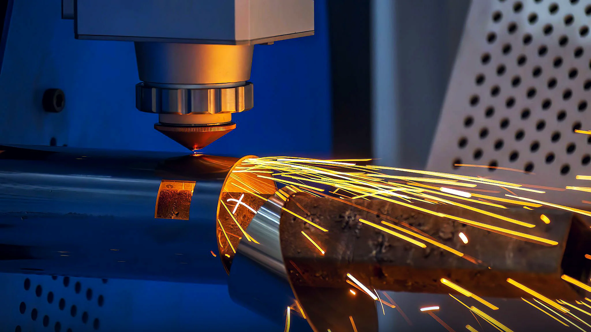
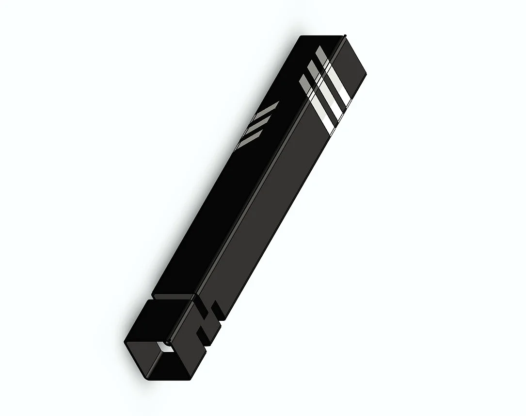
- Tube and profile laser cutting: STEP or IGES — a 3D model carries the exact angle and position of holes on the tube.
- Bent parts: 3D model plus dimensioned PDF or flat DXF.
- No CAD? A photo of a dimensioned sketch is enough to start.
6 DXF checks
- Scale 1:1, units millimetres.
- Closed contours.
- Remove duplicate overlapping lines.
- Dimensions, text and title blocks on a separate layer or removed.
- Arcs and circles as true arcs, not splines.
- Quantity, material and thickness for each part.
Tube and profile drawings
Give the section (e.g. 40×40×2 square tube), length and hole positions from a reference face; state mitre angles and the face they are measured from. Check your section in the capacity checker.
Common mistakes
- Unscaled, undimensioned PDFs
- Sending an assembly drawing instead of part drawings
- Not stating inside or outside dimensions on bent parts
- Old revisions left in the package
Ready? Upload everything at once (ZIP included) via the quote form.
DXF preparation for laser cutting: layers
Keep the contours to be cut on one layer (e.g. CUT) and text or lines to be marked on another (e.g. MARK). Put bend lines on a separate layer and note that they are not cut. With this structure the programmer turns your file straight into a cutting path without redrawing it.
One part per file
Sending each part as its own DXF is cleanest; put the part code, material, thickness and quantity in the file name (e.g. BRACKET-01_S235_3mm_120pcs.dxf). If several parts share one file, make sure they do not touch and that each has its quantity next to it.